
Preventing the Freezing of Vaccines in a Cold Chain
A passive thermal-management case study showing how simple heat-balance equations and finite-element analysis can guide the design of a freeze-preventive vaccine carrier.
Originally published in Mikroniek, nr. 6, 2020 · Akshay Harlalka
Some vaccines lose potency when exposed to freezing temperatures, even though others must be stored at extremely low temperatures. Freezing can be prevented by using a passive thermal buffer layer between the ice packs and the vaccine compartment.
The selection of the material and geometry of this buffer layer is an engineering design task that appears often in precision engineering: simple physics, constrained geometry, material selection, transient behavior, and model verification.
Background
Massive efforts and resources were leveraged globally to develop vaccines for COVID-19. But a vaccine is just a formula. Distributing and administering vaccines to masses effectively is at least as difficult a hurdle to cross. Most vaccines need a cold chain maintaining temperature within a narrow band of 2–8 °C to remain effective.
Counter-intuitively, for some vaccines, especially those containing aluminum salt adjuvants, exposure to freezing can be more damaging than exposure to heat. At freezing temperatures, these adjuvants, which are required to trigger an immune response, cluster together and become damaged, causing the vaccine to lose potency. Loss of vaccine potency leaves vaccinated people at risk of disease.
Various studies have reported that vaccines are frequently exposed to freezing temperatures. In some countries, up to 100 percent of vaccine shipments are known to be exposed to freezing temperatures during their journey across the cold chain.
The problem
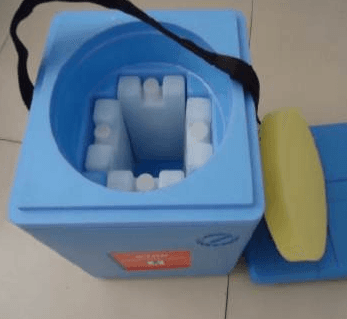
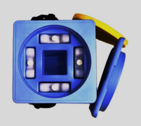
One reason vaccines are exposed to freezing temperatures is the dependence on ice packs to keep the vaccines in the right temperature range. A health worker administering vaccines in a community uses a vaccine carrier to store these vaccines while travelling. The main function of this carrier is to maintain the temperature of the vaccines at 2–8 °C when ambient temperatures can be as high as 43 °C.
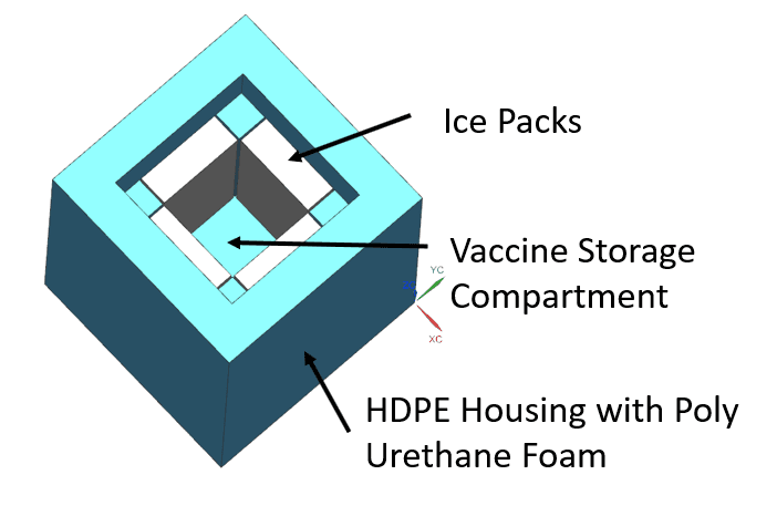
These vaccine carriers are typically made up of an HDPE housing with a CFC-free polyurethane insulation material. Four ice packs are typically used to keep the vaccines at the right temperature. The problem is that when these ice packs are extracted from the freezer, they can be at temperatures as low as −25 °C.
Using these ultra-cold ice packs with vaccines greatly risks freezing. Therefore, healthcare workers are instructed and trained to condition these ice packs to about 0 °C before putting them into the vaccine carrier. However, this step requires time and advanced planning, increases health worker burden, and introduces a risk of human error leading to wastage of precious vaccine resources.
Existing solutions and the gap
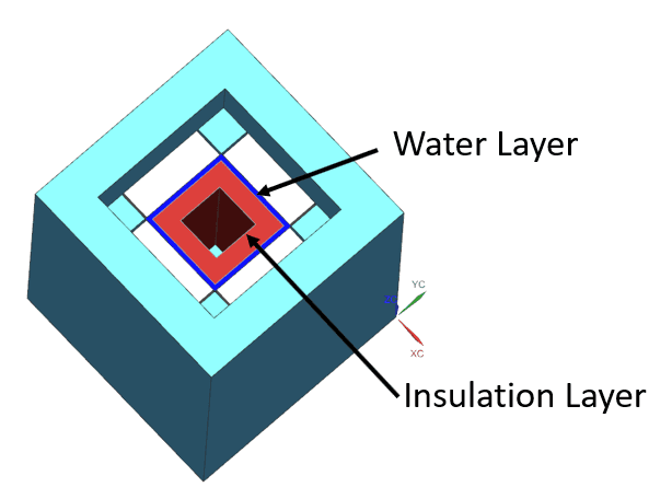
In 2016, PATH, a leading non-profit health organisation, filed a research disclosure detailing the concept of a freeze-preventive vaccine carrier that avoided the need for thermal conditioning of ice packs. A buffer layer between the vaccine storage compartment and the ice packs helped prevent direct contact of the vaccines with the freezing ice packs.
However, adding the thermal buffering layer also reduced the available volume in the vaccine storage compartment.
According to the PQS Verification Protocol for Vaccine Carriers with Freeze Preventive Technology, the minimum available volume in the vaccine storage compartment should be at least 0.5 L for short-range models and at least 1 L for long-range models. However, if the thermal buffering layer is added to existing vaccine carriers, the available volume in the storage compartment falls to 0.42 L.
Vaccine carrier manufacturers who wanted to integrate freeze-preventive barrier technology therefore had to increase the overall size of the vaccine carriers. This reduced the attractiveness of integrating a buffering layer into existing vaccine carriers.
With the whole world rallying resources to develop and distribute vaccines as quickly as possible, it is worth taking a fresh look at whether a cheap, modular thermal buffering layer could be developed without compromising the volume limitations of the vaccine storage compartment. The thermal model described here could aid that discovery.
Analytical thermal model set-up
To optimise the performance of the freeze-preventive thermal buffer given the volume limitations, a thermal model needs to be developed. This model should predict the temperature profile of the key parts of the vaccine carrier system, including the vaccine solution, ice pack, and insulation layer.
Since the temperatures of the ice pack, vaccine solution, and insulation change as a function of time, transient heat-transfer equations are needed. There are a number of ways to solve transient heat-transfer problems, including:
- Lumped-capacitance method.
- Numerical methods.
- Approximate solutions to the heat-diffusion equation using Heisler charts.
- Analytically solving the heat-diffusion equation.
For the analytical model in this article, the 1D unsteady heat-transfer equation was solved using the explicit finite-difference method. The problem was formulated in the Python programming language.
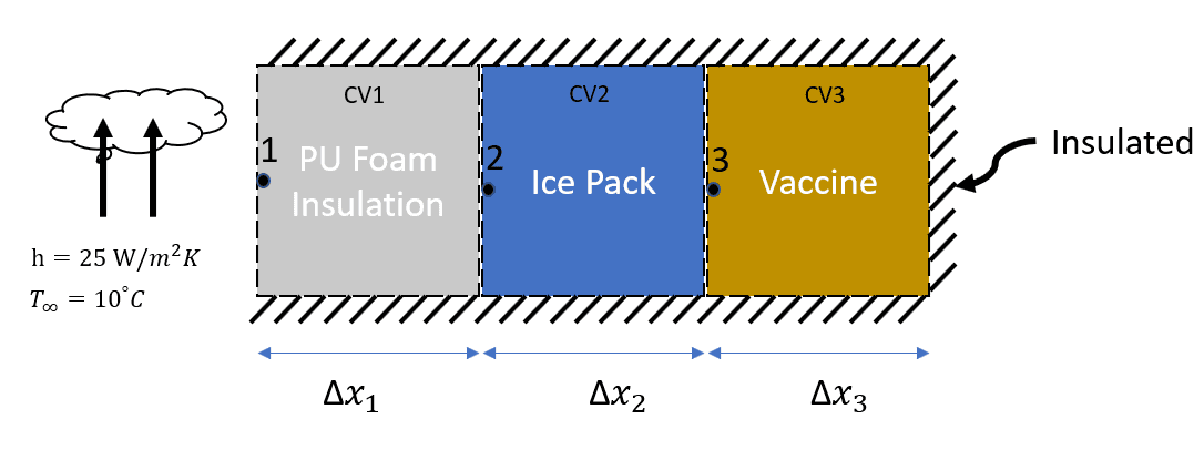
A simplified representation of the thermal model for existing vaccine carriers defines three control volumes: CV1, CV2, and CV3, and three corresponding nodes. Node 1 is exposed to the ambient environment and therefore receives a natural convection boundary condition. All other boundaries are considered perfectly insulated.
The lengths of the different control volumes are given as Δx₁, Δx₂, and Δx₃. Density, specific heat capacity, and thermal conductivity are represented by ρ, c, and k, respectively. To find temperatures at different nodes at various time steps, an energy-balance equation is formulated for each control volume.
Rate of change of internal energy = heat influx due to convection from ambient air + heat influx from conduction from the ice pack.
Solving the energy-balance equations provides the temperature at each node at the next time step using the parameters from the current time step. These equations can then be coded to generate a temperature profile at various nodes as a function of time. If a finer-resolution solution is required, the control volumes can be subdivided further.
| Parameter | CV1: PU foam | CV2: Ice pack | CV3: Vaccine |
|---|---|---|---|
| Length, Δx (m) | 0.0425 | 0.033 | 0.016 |
| Density, ρ (kg/m³) | 200 | 920 | 1,000 |
| Specific heat, c (J/kg·K) | 1,400 | 2,040 | 4,182 |
| Thermal conductivity, k (W/m·K) | 0.026 | 2.22 | 0.6 |
| Initial temperature, Tᵢ (°C) | 10 | −25 | 6 |
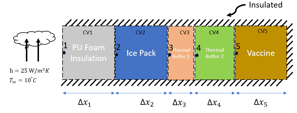
Adding thermal buffers does not change the basic approach. It only increases the model complexity slightly. Instead of three control volumes, the freeze-preventive configuration requires five.
Finite-element thermal model set-up
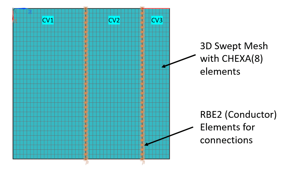
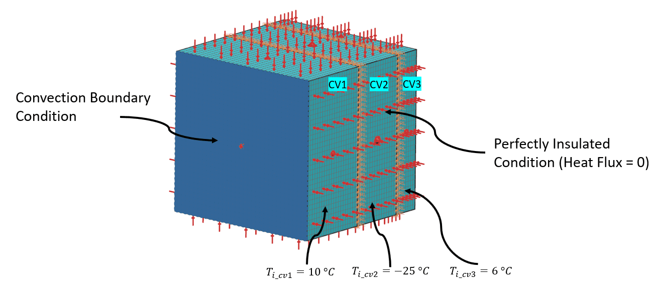
To verify the results generated from the heat-balance equations, a finite-element analysis was performed in NX Advanced Simulation software. A multi-body 3D CAD model representing the lengths of different control volumes in the system was prepared, and the respective material properties were assigned accordingly.
The FEM mesh and boundary conditions were defined such that a convection boundary condition was applied to the ambient-facing side, while the remaining boundaries were treated as perfectly insulated. Initial temperatures of the different control volumes were specified in the model.
Results and discussion
Existing vaccine carrier: no thermal buffer
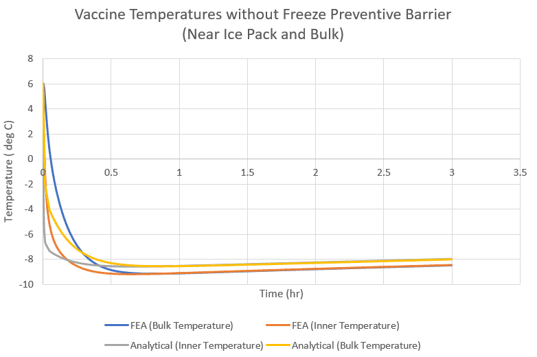
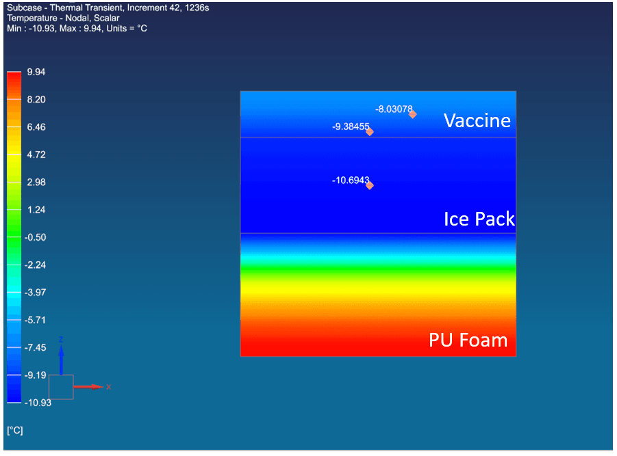
The heat-balance equations were solved using Python, and the temperature data of the vaccine solution as a function of time was exported. Temperature profiles at two different positions on the vaccine solution layer were generated: one near the ice pack, where freezing risk is highest, and the other in the middle of the vaccine solution, representing bulk temperature.
The analytical and FEA solutions matched very well. The graph suggests that vaccine bottles close to the ice pack will be exposed to freezing temperatures. In fact, these vaccine solutions are exposed to freezing temperatures within 30 minutes of being placed in the compartment.
At t = 0.5 h, the temperature of the vaccine solution near the ice pack is −9.3 °C, while the bulk temperature is around −8 °C.
Freeze-preventive vaccine carrier
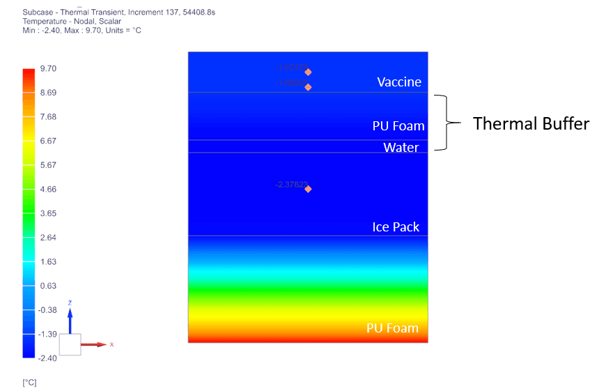
The idea of adding a thermal buffering layer is to increase the thermal mass near the ice packs enough so that the ice packs get conditioned to 0 °C before the vaccine compartment temperature reaches that level.
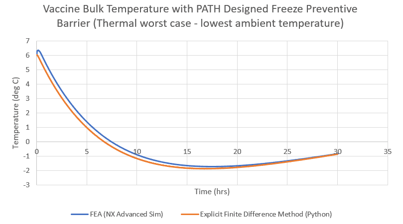
Compared to the temperature profiles for an existing carrier without a thermal buffer, the slope of the vaccine temperature versus time curve is much shallower with the thermal buffer. The lowest temperature the vaccine is exposed to is in the range of −1.6 to −1.8 °C. This is a significant improvement over the previous case, where the lowest temperature was −9.3 °C.
The thermal model does not account for interface resistance to heat transfer, such as the glass bottle that the vaccine is stored in or the HDPE plastic casing that the ice packs are stored in. Including these details could lead to a more accurate solution, probably yielding even higher predicted vaccine temperatures, but it would also add complexity.
Design optimisation of the thermal buffer
Once enough confidence had been established in the FEA model and Python code, various design options were evaluated to determine whether there was room for improvement in the geometry and material selection of the buffer layers.
The current insulation material, PU foam, seems appropriate because of its cost-effectiveness and low thermal conductivity. Water is also appropriate as the other buffer layer because of its high specific heat capacity, which greatly slows down the temperature fall.
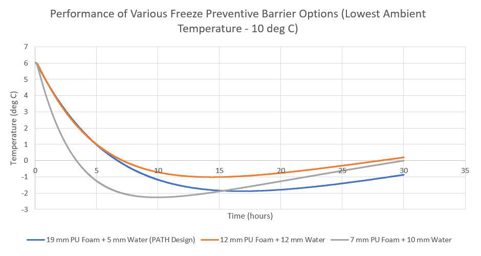
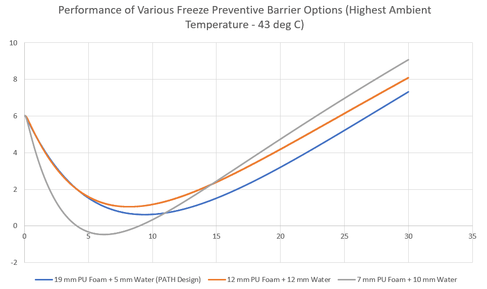
However, after running various design cases, it appears that the division of thicknesses between the two buffer layers can be optimised further. In the PATH design, the water layer is 5 mm thick and the PU foam layer is 19 mm thick. Two other scenarios were evaluated: a 12 mm foam layer with a 12 mm water layer, and a 7 mm foam layer with a 10 mm water layer.
The 12 mm PU foam + 12 mm water combination appears to perform slightly better at low ambient temperatures than the existing PATH design. This design option exposes vaccines to temperatures only as low as −1 °C, compared to −2 °C for the PATH design. Under high ambient temperatures, this option still maintains the vaccine temperature below 8 °C within its specified 30-hour cold life.
There may also be options to reduce the volume footprint of the thermal buffer layer. For example, the 7 mm foam + 10 mm water option performs only slightly worse than the PATH design. It is possible that by increasing the foam thickness slightly, the performance of this option can be made comparable to the PATH design. In such cases, equivalent performance can be reached in a reduced volume footprint, leaving more space for vaccine storage.
Conclusion
The freeze-preventive vaccine carrier was used as a case study to show how passive thermal management solutions can be designed using simple heat-balance equations and FEA models. The excellent correlation achieved with these two approaches is encouraging. Once the model had been verified, various design scenarios were evaluated in order to optimise the design of the thermal buffer layer.
A thermal buffer design option using 12 mm PU foam + 12 mm water appears to outperform the existing design used by manufacturers of freeze-preventive vaccine carriers. This design option reduces the exposure of vaccines to freezing temperatures when ambient temperature is low, while still keeping them cold enough when ambient temperatures are at their peak.
Practitioners in precision engineering can take inspiration from this passive thermal management system: it requires no moving parts, no energy source, and adds minimal cost.
References
- Matthias, D.M., et al., “Freezing temperatures in the vaccine cold chain: a systematic literature review,” Vaccine, 25(20), pp. 3980–3986, 2007.
- “Getting vaccinations to the world’s most hard to reach places,” Dec. 1, 2019. Accessed Nov. 29, 2020.
- “UIFF Vaccine carrier AOV AFVC46 E004/050.” Accessed Nov. 29, 2020.
- “Nilkamal Limited Vaccine carrier LR BCVC46.” Accessed Nov. 29, 2020.
- Research Disclosure: “Freeze-prevention design for vaccine carriers, cold boxes and other passive cold chain equipment to prevent freezing of vaccines, drugs or pharmaceuticals in the cold chain.” Accessed Nov. 29, 2020.
- Requirements Document: WHO PQS E004 VC02-VP.1, Vaccine carrier with freeze-prevention technology PQS verification protocol. Accessed Nov. 29, 2020.